MV/LV Panels & Junction Boxes
Link Boxes
With the development of high voltage and ultra-high voltage applications in power system, the single-core XLPE cables are usually used instead of three-core cables.
Underground power cable system design presents unique design and installation challenges not found in the overhead transmission lines. Poorer thermal dissipation, confined spaces, lack of visibility, more difficult fault diagnosis, circulating earth currents, and frequent joints in an unfriendly environment are all problems that cable engineering design must overcome to deliver a reliable long term installation.
When these cables are in service, circulating currents flows in the sheaths. Large circulating current leads to the big loss & heating in the sheaths and thus reduces the permissible current of the cables. Moreover, it will also enhance the danger in the cable maintenance and reduce the lifetime of the cables or cause the faults by the breakdown of insulation or cable jacket. Lightning, fault currents and switching operations can cause over voltages on the cable sheath.
Link Boxes are used with cable joints and terminations to limit voltage build-up on the sheath & also provide easy access to shield breaks for onsite test purposes. The link box is part of bonding system, which is essential of improving current carrying capacity and human protection.
The link box optimizes loss management in the cable shield, the bonding system is so designed that the cable sheaths are bonded and earthed with or without SVL in such a way as to eliminate or reduce the circulating sheath currents.
To limit the induced voltage in the cable screen to a permissible limit, appropriate screen bonding methods must be selected, depending on the following factors:
- Rated voltage of Circuit,
- Total Length of the circuit,
- Total full load current & fault current of circuit,
- Cable formation flat or trefoil formation.
- The permissible induced voltage for the circuit.
There are different bonding methods available for high voltage single core cables:
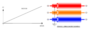
SINGLE POINT BONDING
This is the simplest form of bonding. The sheaths of the three cable sections are connected and grounded at one point only along their length. At all other points, there will be a voltage between sheath and ground that will be at its maximum at the farthest point from the ground bond. The sheaths must therefore be adequately insulated from ground. Since there is no closed sheath circuit, current does not normally flow along the sheaths and no sheath circulation current loss occurs.
BOTH END BONDING
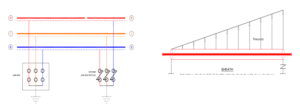
Most Simple and Common method. Cable screen is bonded to earth grid sat both ends (via link box). This eliminates the need for the parallel continuity conductor used in single bonding systems. It also eliminates the need to provide SVL, such as that used at the free end of single-point bonding cable circuits Significant circulating current in the screen Proportional to the core current and cable length and derates cable. Could lay cable incompact trefoil formation if permissible. Suitable for route length of more than 500 Meter. Very small standing voltage in the order of several volts. One End Solidly Grounder Another connected through Sheath Voltage Limiters
SPLIT SINGLE BONDING SYSTEM
It is also known as double length single point bonding System. Cable screen continuity is interrupted at the midpoint and link boxes with SVLs at isolation joints. An Earth continuity conductor is layer connecting earthing point of all 3 link boxes.

CROSS BONDING
Transposing the position of the cables as shown in figure below, relative to each other at every joint bay. This ensures that sheath induced voltage is balanced in each cable. For cross bonding, the cable length is divided into three approximately equal sections. Each of the three alternating magnetic fields in ducesa voltage with aphase shift of 120" in the cable shields. The cross bonding takes place in the link boxes. Ideally, the vectorial addition of the induced voltages results in Uires = O.lnpractice, the cable length and the laying conditions will vary, resulting in a small residual voltage and a negligible current. Since the reisno current flow, the reare practically no losses in the screen. The total of the three voltages is zero, thus the ends of the three sections can be grounded.
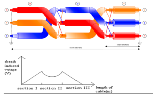
Cross bonded link box are installed at every transposition point/joint to transpose the metallic cable sheaths, connecting sheath of one phase to other as per transposition pattern. This cross connection of the sheaths effectively cancels circulating sheath currents. Surge voltage limiters or arrestors are routinely used between sheaths and earth to limit induced voltage spikes that may occur during transient and fault conditions.
PTE Link Boxes
PTE Link Boxes are used by Utilities, Contractors and Cable Manufacturers across GCC.
Using modern manufacturing technology, PTE can deliver a robust design capable of withstanding extreme Electrical, Mechanical & environmental stresses a link box may face.
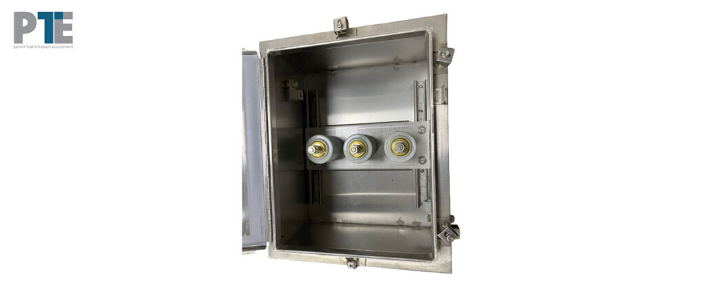
PTE's designs are type tested as per latest IEC standards, enclosure made of SS-316, Brass and Fiber Glass. 100% routine testing process ensures that each link box provides, high insulation, Low contact resistance & a moisture free environment for the cable metal sheath connections and links.
PTE link boxes are designed using removable isolation links to provides the operator improved access to the cable connections and links, thus reducing installation and testing times.
Different cable sheath earthing practices require a number of link box designs. These designs are suitable for either single core or coaxial bonding cables, and can be directly earthed or earthed through surge voltage limiters.


DESIGN FEATURES
- Compact Design
- IP-67 Degree of Protection.
- Made of Stainless Steel, Fiber Glass & Brass.
- Custom design cable glands and lugs sizes.
- Underground & above ground installation designs.
- Indoor & outdoor designs.
- Removable disconnecting links for onsite testing.
- Design Manufactured & Tested as per International Standards.
IEEE STD-575-1988
IEC 60529 for Ingress Protection.
IEC-60060-1-1989 for Insulation level.
IEC-60230 for Lighting impulse.
Short Circuit Withstand –IEC-62271-1
Sheath Voltage Limiter (SVL)
These special surge arresters are of relatively low continuous operating voltage.
The correct sheath voltage limiter (SVL) is dictated by the need to withstand the highest external transient voltages that can occur from, short circuit fault, switching surges and lightning, which generate damaging over-voltages.
The SVL used in PTE link boxes are manufactured by Insulect (AK Power) Australia, these zinc oxide SVLs are capable of withstanding high current surges and have the capacity to absorb and dissipate this energy.
Key Features Sheath Voltage Limiters(SVLs)
These special surge arresters are of relatively low continuous operating voltage.
The correct sheath voltage limiter (SVL) is dictated by the need to withstand the highest external transient voltages that can occur from, short circuit fault, switching surges and lightning, which generate damaging over-voltages.
These ZnO (zinc oxide) SVLs are capable of withstanding high current surges and have the capacity to absorb and dissipate this energy.
|
SL. NO. |
Item Code |
Single Line Diagram |
Description |
SVL Earthing Option |
Gland Entry |
Encluture |
|
1. |
PTE-DE-1S
|
|
1/1 Way-Single Phase Direct Earthing Without SVL
|
Direct Earthing
|
1 in, 1 out |
Stainless Steel, Brass & Fiber Glass
|
|
2. |
PTE-ES-1S |
|
1/1 Way-Single Phase Direct Earthing With SVL
|
SVL Protection
|
1 in, 1 out
|
Stainless Steel, Brass & Fiber Glass
|
|
3. |
PTE-DE-3S |
|
3/1 Way-Three Phase Direct Earthing Without SVL
|
Direct Earthing
|
3 in, 1 out
|
Stainless Steel, Brass & Fiber Glass
|
|
4. |
TE-ES-3S |
|
3/1 Way-Three Phase With 3 SVLs |
SVL Protection
|
3 in, 1 out
|
Stainless Steel, Brass & Fiber Glass
|
|
5. |
PTE-DE-6S |
|
6/1 way-3 Phase Direct Earthing for joints-Without SVL (Coaxial Bonding Cable)
|
Direct Earthing
|
3 in, 1 out
|
Stainless Steel, Brass & Fiber Glass
|
|
6. |
PTE-CES-6S |
|
6/1 Way- 3 Phase Cross bonding for Joints with 3 SVLs (Coaxial Bonding Cable)
|
SVL Protection
|
3 in, 1 out
|
Stainless Steel, Brass & Fiber Glass
|
|
7. |
PTE-CES-6S1 |
|
6/1 Way- 3 Phase Cross bonding for Joints with 3 SVLs (Single Core Bonding Cable)
|
SVL Protection
|
6 in, 1 out
|
Stainless Steel, Brass & Fiber Glass
|
|
8. |
PTE-SES-6S |
|
6/1 Way- 3 Phase Straight for Joints with 3 SVLs (Coaxial Bonding Cable)
|
SVL Protection
|
6 in, 1 out
|
Stainless Steel, Brass & Fiber Glass
|
|
9. |
PTE-SES-6S1 |
|
6/1 Way- 3 Phase Straight for Joints with 3 SVLs (Single Core Bonding Cable)
|
SVL Protection
|
3 in, 1 out
|
Stainless Steel, Brass & Fiber Glass
|
|
10. |
PTE-DE-1S |
|
1/1 way-Single Phase Direct Earthing Without SVL
|
Direct Earthing
|
6 in, 1 out
|
Stainless Steel, Brass & Fiber Glass
|
|
11. |
PTE-SESS-6S1 |
|
6/1 Way- 3 Phase Straight for Joints with 6 SVLs (Coaxial Bonding Cable)
|
SVL Protection
|
3 in, 1 out
|
Stainless Steel, Brass & Fiber Glass
|
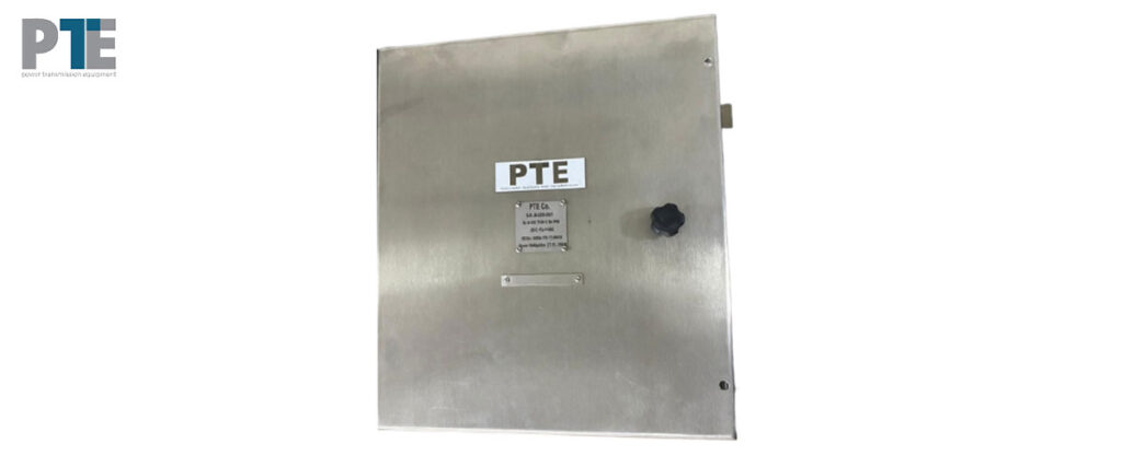
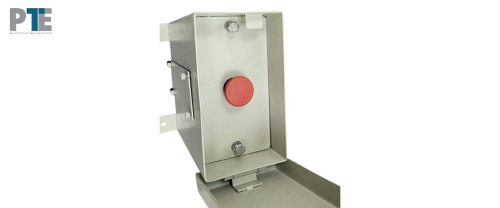
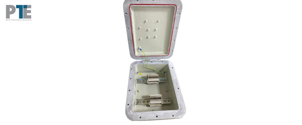
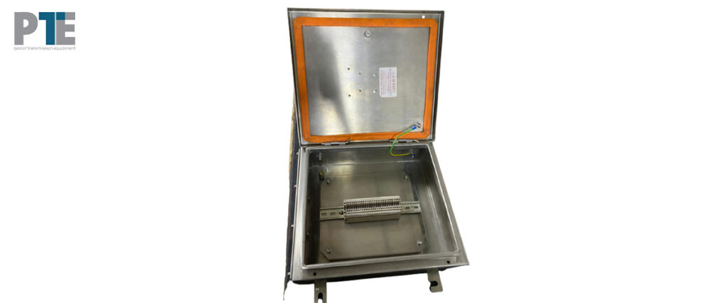
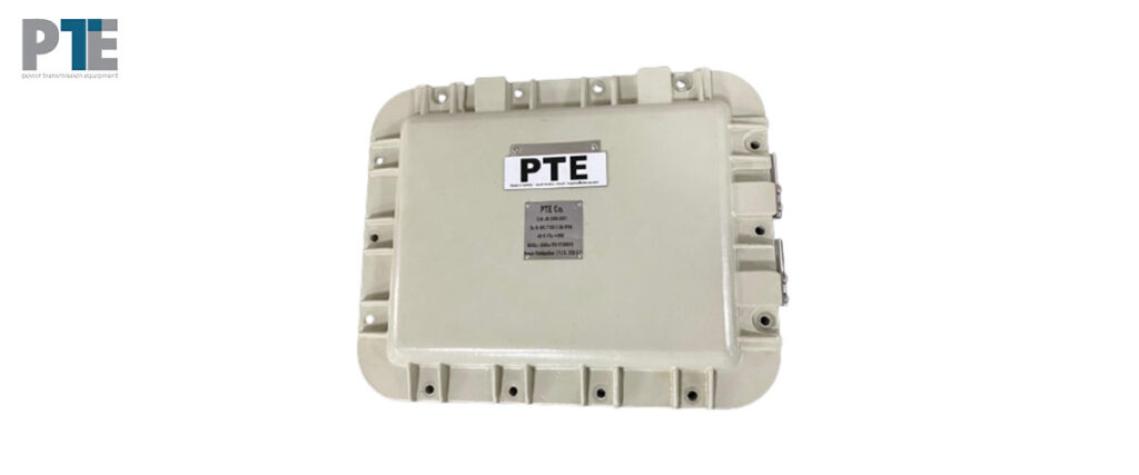
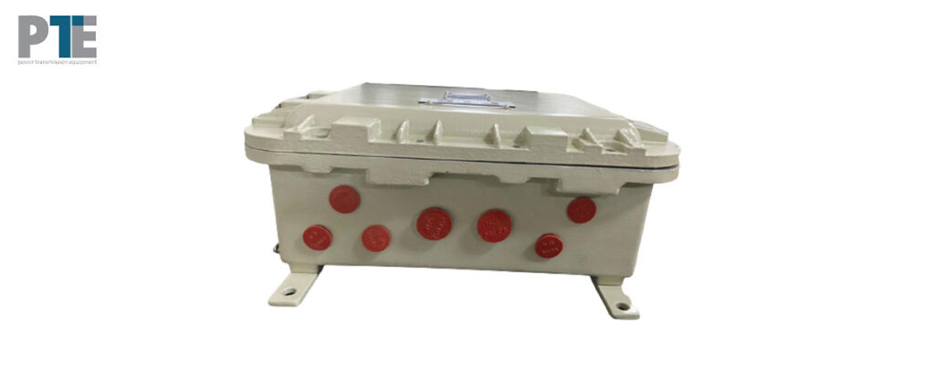
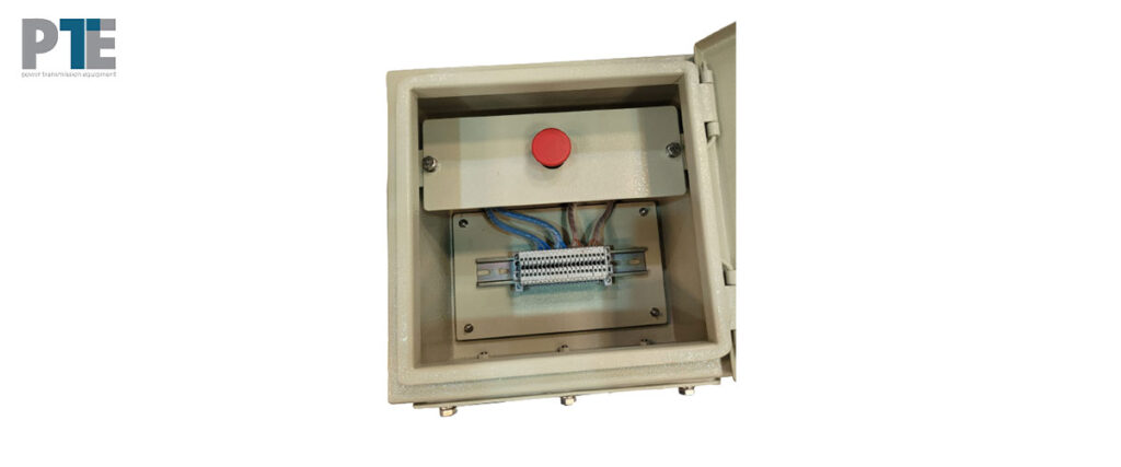
An electrical junction box / marshalling box / disconnector box is an enclosure housing electrical connections to protect the connection and provide a safety barrier depending on application area classification made of aluminum, fiber glass & stainless steel. PTE Jeddah Saudi Arabia manufactures junction boxes, Marshalling Boxes, Heat Insulated out door enclosures, cathodic protection & earthing boxes used in several classified areas like Explosion proof, fireproof, IP65, IP66, IP67, IP68, NEMA-4, NEMA-5, NEMA-6, NEMA-7 & NEMA-8.
